
To connect a solar sensor circuit, one must follow systematic approaches regarding the components and pathways involved in the assembly and operation of the circuit. 1. Identify the solar sensor components, 2. Connect the solar panel appropriately, 3. Wire the sensor to the circuit board correctly, 4. Test the assembly for functionality. Each of these aspects plays a crucial role in ensuring efficient performance and reliability of the solar sensor circuit.
Elaborating further on the first point, understanding the various components involved in a solar sensor circuit is essential. The solar panel itself converts sunlight into electric energy; this energy powers the sensor and often a microcontroller. Choosing appropriate components is fundamental, so ensuring compatibility among them can determine the overall success of your project.
1. COMPONENTS OF A SOLAR SENSOR CIRCUIT
Creating a solar sensor circuit begins with a thorough understanding of the essential components. The core elements usually consist of solar panels, sensors, a microcontroller, resistors, and connectors. Each component serves a distinct purpose and contributes to the circuit’s performance.
1.1 SOLAR PANELS
Solar panels are designed to convert sunlight into electrical energy through photovoltaic cells. The effectiveness of solar panels can be measured in terms of efficiency, size, and output voltage. When selecting solar panels for your circuit, you should consider both the intensity of sunlight in your region and the power requirements of the sensor.
1.2 SENSORS
Sensors detect changes in the environment and convert those changes into signals for the microcontroller, which processes the information. Common types of sensors used in solar circuits include light sensors and temperature sensors. Depending on the application, the choice of the sensor can greatly affect performance, such as whether you require a high sensitivity sensor for precise measurements.
1.3 MICROCONTROLLERS
Microcontrollers serve as the brain of the circuit, processing the signals received from the sensors. They can be programmed to carry out specific functions and are essential for reading data, making decisions, and powering actuators. Choosing the right microcontroller depends on the complexity of your project, including processing speed and available input/output ports.
1.4 RESISTORS AND CONNECTORS
Resistors are used to limit the current flow and protect sensitive components from overcurrent, while connectors ensure that all components in the circuit are properly linked together. Using the correct resistor values is vital for preventing damage to the circuit. Make sure to review the specifications for each component to choose the appropriate resistances.
2. ASSEMBLY OF THE SOLAR SENSOR CIRCUIT
Once the components have been gathered, the next step involves assembling the circuit. This phase requires meticulous attention to detail to guarantee that everything is connected correctly and securely.
2.1 CIRCUIT LAYOUT
Designing a circuit layout is fundamental to ensuring that the connections are practical and organized. Using a breadboard initially can help in visualizing the arrangement. It allows temporary connections, making it easier to modify the circuit before finalizing it on a printed circuit board (PCB). Taking time to plan the layout in advance can prevent mistakes that could lead to circuit failures.
2.2 CONNECTING COMPONENTS
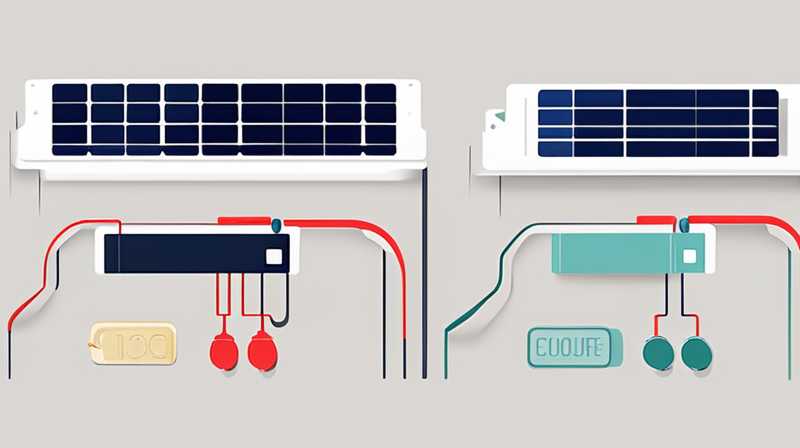
Begin by connecting the solar panel to your microcontroller. Typically, the positive terminal of the solar panel connects to a designated input terminal on the microcontroller, while the negative terminal connects to the ground. After that, connect the sensors. Follow up by wiring resistors between the sensors and the microcontroller according to your circuit design. Ensure that each connection is secure and that wires are not tangled, as this can lead to operational failures.
3. PROGRAMMING THE MICROCONTROLLER
Programming the microcontroller is where the magic of the solar sensor circuit truly happens. This is the phase in which you determine how the system reacts to various environmental conditions.
3.1 CHOOSING A PROGRAMMING LANGUAGE
You will want to select a programming language that suits your microcontroller. Many modern microcontrollers can be programmed using various languages such as C, Python, or JavaScript, depending on the platform. The complexity of your application may dictate which language is most appropriate.
3.2 WRITING THE CODE
Once the programming language is decided upon, initiate the coding process. Coding typically involves defining how the sensor reads data, how the microcontroller processes this data, and how it communicates with other components. Keep in mind that comments and documentation within your code can significantly ease future debugging and updates. This part may require various iterations until you achieve a desirable result.
4. TESTING THE SOLAR SENSOR CIRCUIT
After completing the assembly and programming stages, it’s crucial to put the system to the test. This phase helps identify any potential issues that may not have been apparent during earlier stages.
4.1 INITIAL FUNCTIONAL TESTING
Start by ensuring that the solar panel is receiving adequate sunlight. Check if the solar sensor circuit outputs as expected under varying light conditions. Utilize a multi-meter to verify that the voltage levels correspond with your circuit design. Properly calibrating the sensors is also vital during this testing phase as inaccurate readings can lead to failures later on.
4.2 LONG-TERM TESTING
After initial tests, subject your solar sensor circuit to prolonged testing under real-world conditions. Monitor its performance day after day to gather data about its reliability and responsiveness. Ensure that the temperature fluctuations and changing light conditions don’t adversely affect the functioning of your system. Long-term testing gives an insightful perspective on the efficacy and durability of your overall design.
FREQUENTLY ASKED QUESTIONS
WHAT TYPE OF SOLAR PANEL SHOULD I USE?
The type of solar panel one selects depends on the application and power needs of the circuit. Different types come with varying efficiencies, which can impact performance. For small projects, monocrystalline panels are highly efficient, while polycrystalline options are often more affordable. However, it’s essential to consider the specific voltage and current requirements your circuit demands. Ensuring compatibility with your components will also dictate the best selection. For larger projects, more robust solar panels may be required. Overall, understanding these factors will help you choose the most suitable solar panel for your needs.
HOW DO I TROUBLESHOOT A SOLAR SENSOR CIRCUIT?
To troubleshoot issues within a solar sensor circuit, systematically check each component’s connections and functionality. Start by verifying the solar panel is receiving adequate sunlight and generating power. Use a multi-meter to check voltage across the solar panel and ensure it meets expected levels. Next, examine the wiring between the solar panel, sensors, and microcontroller for any loose connections. Check if the sensors are calibrated correctly and whether the microcontroller is running the code as intended. If difficulties persist, consult the component datasheets, which often provide diagnostic tips. Patience and thorough examination are key when diagnosing circuit issues.
HOW CAN I IMPROVE THE EFFICIENCY OF MY SOLAR SENSOR CIRCUIT?
Improving the efficiency of a solar sensor circuit can be achieved through several strategies. Firstly, selecting high-quality solar panels with better efficiency ratings can significantly enhance energy capture. Additionally, ensuring correct alignment towards the sunlight can further increase effectiveness. Another method is using low-power components and microcontrollers, which can minimize energy consumption. Implementing energy storage systems, such as batteries, can also allow excess energy to be utilized when sunlight is not available. Optimization in both hardware and programming can lead to a more effective and reliable solar sensor circuit.
In summary, establishing a functional solar sensor circuit necessitates careful consideration of its components, meticulous assembly, proficient programming, and sound testing strategies. Ensuring all components work harmoniously enhances the overall performance of the system. It is critical to note that the quality of the solar panel, coupled with understanding the specific requirements of each element involved, directly influences the efficacy and lifespan of the circuit. The details outlined throughout this discussion emphasize that careful planning and execution at every phase will yield rewarding results. Prioritizing thorough component selection, precise wiring, adept programming, and rigorous testing ultimately leads to a well-functioning solar sensor circuit that meets its intended purpose. Embracing these principles can spark innovation, making solar technology accessible for various applications.
Original article by NenPower, If reposted, please credit the source: https://nenpower.com/blog/how-to-connect-solar-sensor-circuit/
